Abstract
In this article author considers aspects of implementing RS-232 communication routines in Microchip PIC microcontroller’s software, describes technique to achieve high speed (>=115200) of transmitting and receiving data, dwells on hardware (CTS/RTS) flow control and illustrates how assembler macro may be used to generate transmitter and receiver routines for any given speed at any given frequency. A sample application supplied with the article provides tests for transmitter and receiver routines for baud rates 230400, 115200, 56700 and 38400 at clock frequency 4 MHz.
Take-off run
The application I am developing needs to send data (2-3 bytes) to PC between events in the external environment. Time between two consecutive events does not allow using even 115200 baud. Speeding up the PIC definitely would not help and using a different protocol is not desirable. While configuring COM port, I have noticed that there are higher baud rates available: 230400, 460800, and 921600. I tried to test them in a terminal application, but it did not work, because, as it turned out, the original Windows driver does not allow selecting these speeds regardless of whether UART chip support them or no. I have searched the web and found alternative drivers [3] that enables higher baud rates supported by UART chip. Now the goal is to implement this speed in PIC. In which one? Most popular among hobbyists 16F84A would fit for this purpose.
Diving to bottom
Baud rate 230400 requires one bit to be 4.34 ?µs long with allowed up to ?± 20% derivation in waveform. Instruction cycle at 4 MHz is 1?µs log, thus, bit should be 4.34 cycles long. Unfortunately, PIC does not operate in fractional instruction cycles, so we have to round it. However, being rounded to 4 it brings cumulative error, which at bit 3 already gives 50% error and 75% per 8 bits. What possible options for handling this problem? Most obvious is speeding up PIC to 10MHz. Second option is slowing down to 3.68 MHz clock. Third option is to use unequal bit lengths.
Varying the length
Bit length requirement 4.34 ?µs ?± 20% allows some variation: 3.47 ??“ 5.21. So, to avoid cumulative error we may implement some bits as 4 cycles long and some others as 5. Table 1 shows which bits should be longer. This approach, (let’s name it bit aligning), gives maximum bit-timing error of 8.8%.
Table 1 . Bit lengths for 230400
| Bit | Time | Cycle | Length |
| Start | 4.34 | 4 | 4 |
| 0 | 8,68 | 9 | 5 |
| 1 | 13,02 | 13 | 4 |
| 2 | 17.36 | 17 | 4 |
| 3 | 21.70 | 22 | 5 |
| 4 | 26.04 | 26 | 4 |
| 5 | 30.38 | 30 | 4 |
| 6 | 34.72 | 35 | 5 |
| 7 | 39.06 | 39 | 4 |
| Stop | 43.40 | 43 | 4 |
Driving the port
Next challenge is to drive port within 4 instructions. Most commonly used approach (roll data, test carry, branch to BSF or BCF) is too long to fit in 4 cycles. On PICLIST (see [1]) I found a brilliant idea suggested by Regulus Berdin. The core of his idea is to use XORWF PORT, F and to drive port only if level has to be changed. This requires the data byte to be prepared so it indicates level alternations instead of levels. He does it as simple as
| rrf | data, W | ; prepare data for output: | |
|
xorwf | data, F | ; '1' in DATA means toggle port |
This code puts first data bit into carry (STATUS,C) while bits 0-6 in data indicate level alternations, which are used as the following:
| btfsc | data, 1 | ; test data | |
| xorwf | port, F | ; send bit |
There is no room left for any bit counting (which takes 3 cycles), so we cannot use a loop to send a byte. Instead we will use linear code (unrolled loop). But before we may start writing this routine we have to decide
To space or to mark
RS-232 protocol operates in terms of SPACE and MARK. SPACE is positive voltage, indicating logical 0. MARK is negative voltage indicating logical 1 and this is also an idle state of the interface lines. PIC cannot be directly connected to RS-232 lines, so there should be some intermediate hardware that converts TTL levels to RS-232. Depending on implementation, this hardware may either drive SPACE on level 0 or on level 1. Similarly, it may convert SPACE either to 0 or 1. For simplicity, we assume that SPACE is driven by logical 0.
First flight-shot
Let's make our transmitter routine, assuming that the data byte is passed in W, inserting delay n instead of nop delays.
| movwf | data | ; put data to rotation buffer | |
| rrf | data, W | ; prepare data for output: | |
| bcf | port, 0 | ; 0: sending start bit | |
| xorwf | data, F | ; 1: '1' in DATA means toggle port | |
| movlw | 1 | ; 2: load port-toggling mask | |
| skpnc | ; 3: first bit is already in C | ||
| xorwf | port, F | ; 4: send bit 0 | |
| delay | 3 | ; 5, 6, 7 | |
| btfsc | data, 0 | ; 8: test data | |
| xorwf | port, F | ; 9: send bit 1 | |
| delay | 2 | ; 10, 11 | |
| btfsc | data, 1 | ; 12: test data | |
| xorwf | port, F | ; 13: send bit 2 | |
| delay | 2 | ; 14, 15 | |
| btfsc | data, 2 | ; 16: test data | |
| xorwf | port, F | ; 17: send bit 3 | |
| delay | 3 | ; 18, 19, 20 | |
| btfsc | data, 3 | ; 21: test data | |
| xorwf | port, F | ; 22: send bit 4 | |
| delay | 2 | ; 23, 24 | |
| btfsc | data, 4 | ; 25: test data | |
| xorwf | port, F | ; 26: send bit 5 | |
| delay | 2 | ; 27, 28 | |
| btfsc | data, 5 | ; 29: test data | |
| xorwf | port, F | ; 30: send bit 6 | |
| delay | 3 | ; 31, 32, 33 | |
| btfsc | data, 6 | ; 34: test data | |
| xorwf | port, F | ; 35: send bit 7 | |
| delay | 3 | ; 36, 37, 38 | |
| bsf | port, 0 | ; 39: sending stop bit | |
| return |
As we now see, this routine needs delays for 2 and 3 instruction cycles. If we use simple nop to make delays, it would take additional 20 words of program memory making routine 43 words long. Let us consider alternatives to save a word or two.
| movwf | data | ; put data to rotation buffer | |
| rrf | data, W | ; prepare data for output: | |
| bcf | port, 0 | ; 0: sending start bit | |
| xorwf | data, F | ; 1: '1' in DATA means toggle port | |
| movlw | 1 | ; 2: load port-toggling mask | |
| skpnc | ; 3: first bit is already in C | ||
| xorwf | port, F | ; 4: send bit 0 | |
| goto | $+1 | ||
| nop | |||
| btfsc | data, 0 | ; 8: test data | |
| xorwf | port, F | ; 9: send bit 1 | |
| goto | $+1 | ||
| ... | |||
| btfsc | data, 6 | ; 34: test data | |
| xorwf | port, F | ; 35: send bit 7 | |
| goto | $+1 | ||
| nop | |||
| bsf | port, 0 | ; 39: sending stop bit | |
| return | ; Routine length: 35 words |
Sighting the limits
What is the highest speed one may achieve with this approach? Marginal timing error 20% is reached when it is equal to a half of the instruction cycle, which gives 2.5 IC per bit or 400000 baud. Generalizing, we may say that BAUD RATE = CLOCK/10 is the estimated limit. What is the lowest speed that requires bit aligning? The problems begin when cumulative timing error reaches 20%. Averaging bit error to 0.5 IC, we get equality †9/2 IC = bit*0.2 that gives us 22.5 cycles per bit, or 44K baud @ 4 MHz and 178K baud @ 10 MHz. Of course, it depends on rate/clock ratio and, for some particular cases, there may be no need in bit alignment. Table 2 shows timing errors1 with equal and aligned loops for two most used clock frequencies and five highest baud rates. For comparison purposes, it also lists lowest bit errors achieved with hardware UART2.
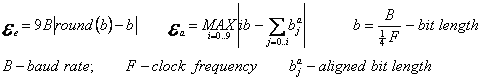
Table 2 . Timing errors
| 4 MHz | 10 MHz | |||||
| equal | aligned | UART | equal | aligned | UART | |
| 57600 | 19% | 2.7% | 8.5% | 8% | 1.0% | 1.4% |
| 115200 | 33% | 5.1% | 8.5% | 12% | 2.3% | 8.5% |
| 230400 | 71% | 8.8% | 8.5% | 12% | 4.1% | 9.6% |
| 460800 | 71% | 23% | - | 71% | 8.3% | - |
| 921600 | - | - | - | 95% | 16% | - |
Considering 10% error in bit timing as acceptable we may make conclusion that the bit alignment is required starting from baud rate 57600 @ 4 MHz and 115200 @ 10 MHz.
Slowly emerging
Now let us try to apply this approach to lower speeds. With 115200 we get cycle lengths 9 8 9 9 8 9 9 8 9. So, sending the start bit may be the very first instruction and all preparation may be done while expiring the start bit.
| bcf | port, 0 | ; 0: sending start bit | |
| movwf | data | ; 1: put data to rotation buffer | |
| rrf | data, W | ; 2: prepare data for output: | |
| xorwf | data, F | ; 3: '1' in DATA means toggle port | |
| movlw | 1 | ; 4: load port-toggling mask | |
| delay | 3 | ; 5, 6, 7 | |
| skpnc | ; 8: first bit is already in C | ||
| xorwf | port, F | ; 9: send bit 0 | |
| delay | 6 | ; 10, 11, 12, 13, 14, 15 | |
| btfsc | data, 0 | ; 16: test data | |
| xorwf | port, F | ; 17: send bit 1 | |
| delay | 7 | ; 18, 19, 20, 21, 22, 23, 24 | |
| ... | |||
| xorwf | port, F | ; 78: send bit 7 | |
| delay | 8 | ; | |
| bsf | port, 0 | ; 87: sending stop bit | |
| return | ; Routine length 30 words |
Four delay intervals are needed: 3, 6, 7 and 8. We still cannot use a counter for measuring delays because loading the counter would discard the port-toggling mask. Call to a subroutine takes at least 4 IC, so we may declare a subroutine with three entrees that, along with calls to d8, d7, d6, will implement these delays:
| d8 | nop | ||
| d7 | nop | ||
| d6 | goto | $+1 | |
| return | ; Routine length 4 words |
Next in the list is 57600 with cycle lengths 17 18 17 17 18 17 18 17 17. The bit length is already long enough to use loop. However, this loop should also use some kind of aligning. What code may give us desired results? The following sequence is executed in 3 or 4 IC, depending on the content of align file:
| rrf | align, F | ; 1: rotate align bits | |
| skpnc | ; 2: align if indicated by C | ||
| goto | $+1 | ; 3: this instruction alings the cycle |
Thereby, if we make a loop of 17 IC long and put B'001010010' into align, we get bit lengths as required. We also have to change the way we test data bit. Previously used btfsc data,<i> will not work in the loop, so data should be rolled bit by bit into C. This requires changing data preparation. In previous examples our code places bit 0 into carry, now all bits must be in the file register. Considering all this, the routine will look like:
| bcf | port, 0 | ; 0: sending start bit | |
| movwf | data | ; 1: put data to rotation buffer | |
| clrc | ; 2: C will be rolled in, so clear it | ||
| rlf | data, W | ; 3: prepare data for output | |
| xorwf | data, F | ; 4: '1' in DATA means toggle port | |
| movlw | .8 | ; 5: load bit count | |
| movwf | count | ; 6: into counter | |
| movlw | B'00101001' | ; 7: load alignment bits, not including start bit | |
| movwf | align | ; 8: load to alignment rotation file | |
| delay | 5 | ; 9, 10, 11, 12, 13 | |
| _bit | movlw | 1 | ; 14: load port-toggling mask |
| rrf | data, F | ; 15: put data bit into C | |
| skpnc | ; 16: test data bit | ||
| xorwf | port, F | ; 17: send bit | |
| rrf | aling, F | ; 1: rotate align bits | |
| skpnc | ; 2: align if indicated | ||
| goto | $+1 | ; 3: this instruction alings the cycle | |
| delay | 7 | ; 4, 5, 6, 7, 8, 9, 10 | |
| decfsz | count,F | ; 11: counting bits | |
| goto | _bit | ; 12: | |
| stop | delay | 4 | ; 13, 14, 15, 16 |
| bsf | port, 0 | ; 17: sending stop bit | |
| return | ; Routine length 23 words |
The shortest bit length we may achieve with this loop is 10 instruction cycles. One may notice, that movlw 1, being placed out of the loop, would make it even shorter: 9 cycles. However there is a reason to keep it inside of the loop, which I'll tell in the next chapter.
Seizing immense
If we take an arbitrary clock frequency and an arbitrary baud rate, the transmitter routine would still look similar to one of the examples given above. The only differences would be specific delays. It is reasonable to let compiler calculate these delays and place them in the routine body. Now our challenge is to write a macro that would produce transmitter routine for any specified baud rate at any specific clock frequency. What would be input for this macro? Clock frequency, baud rate, number of bits, port, pin, and space level (0 or 1). Since all applications in PIC work on the same clock J, we may pass it to our macro via a global constant or a definition. Other parameters may not be considered as global. For example, there may be a need of two transmitter routines sending via different ports with different speeds (such as main communication channel (slow) and debug output channel (fast)). Considering this, the first line of macro may look like:
RS_bodySEND macro speed, bits, port, pin, spacelvl
Next what we have to do is calculating instruction cycles per bit (CBP) and alignment. CBP is simply clock divided by speed (with fractional part ignored). To calculate alignment we will code a loop that accumulates and compares required bit lengths to the length achieved with CBP. If difference is greater than 0.5 IC, an alignment bit is set.
RS_calcCONST  macro speed, bits

  local cycles, align

  local i, c

cycles = CLOCK  / (speed / .25)          ; ((CLOCK / 4) /  speed ) * 100

  RS_CYCLESPERBIT  set cycles / .100

  i = 0

  c = 0

  align = 0

  while( i <= bits )                    ; bit alignment for all bits + stop bit

  c = c +  RS_CYCLESPERBIT

  i++

   if( (i * cycles) - (c * .100) >= .50 )

align = align  | (1 << (i-1) )           ; set alignment bit

  c++

   endif

 endw

  RS_BITALIGNMENT  set align

 endm
Now we have to decide which template routine to use: looped or linear. RS_CYCLESPERBIT gives as a guidance: 10 and more may be achieved with the looped, lesser – only with the linear. As a result, the main macro is ready:
RS_bodySEND macro speed, bits, port, pin, spacelvl
RS_calcCONST speed, bits
RS_#v(speed)SEND
movwf RS_DATA ; put data to rotation buffer
if(RS_CYCLESPERBIT < .10)
RS_bodySEND2_9 speed, bits, port, pin, spacelvl
else
RS_bodySEND10_H speed, bits, port, pin, spacelvl
endif
if( spacelvl )
bcf port, pin ; sending stop bit
else
bsf port, pin ; sending stop bit
endif
endm
RS_DELAY0WC
| addlw | -.1 | ; 4 | |
| skpz | ; 5 | ||
| goto | RS_DELAY0WC | ; 6 | |
| return | ; 7 |
Together with WREG loading, it takes W*4+4 cycles and has limit of 1028 IC and precision of 4 IC. We may enhance its precision with additional entries:
RS_DELAY3WC
nop
RS_DELAY2WC
nop
RS_DELAY1WC
nop
RS_DELAY0WC
...
| movlw | n/4 | |
| call | RS_DELAY<n&3>WC |
To provide RS_bodySEND macro with proper delay routines we may add code to RS_delay macro that will collect all needed entries by setting a flag in a constant and define RS_delays macro that will examine this constant and generate only needed delay routines and their entries, saving code space. With all these tricks, application code will look like this:
#define CLOCK .4000000
RS_SEND225K

     RS_bodySEND .230400, .8, PORTA, 1, 0

     return

     RS_delays
Simulating waves
It is time to see if these routines will work at all. For this purpose I have created a unit test application that, depending on selection, outputs data with baud rates 57600, 115200 and 230400 and ran it in the simulator. Simulator traces are then visualized with self-made SIMCHART application and are shown on figures 1-3. They appear to be OK. Will they work in silicone? They should, but let us defer this question and consider the receiver routine first.
Figure 1. 57600, start bit (17IC) and bit0 (18IC)
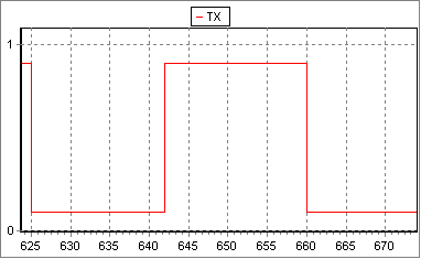
Figure 2. 115200, start bit (9IC), bit0 (8IC), bit1 (9IC), bit2 (9IC)
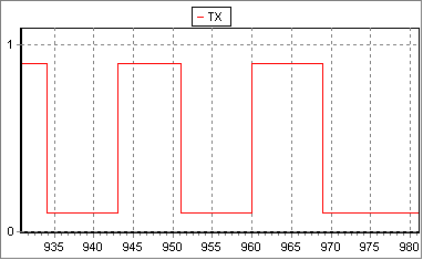
Figure 3. 230400, start bit (4IC), bit0 (5IC), bit1(4IC), bit2(4IC),…
Listening air
Before we will be able receiving data with high speeds, we have to decide how we will detect the start bit. Basically, there are two ways: via interrupt or in a polling loop. Let us analyze pos and cons for these two solutions. The shortest polling loop is:
btfsc port, pinHowever, this loop polls the pin every third cycle and, when it exists, start bit already hold for 2–4 IC. Port reading itself also has some non-deterministic period: PIC reads data from a port on the raising edge of Q2, (see [4], Figure 9.7) which gives us non-deterministic period ‑0.75 – +0.25 IC. Altogether polling loop error, bit mistiming (0.4 IC) and non-determinism make 1.2 – 4.3 IC (or 2.75±1.55) and contributes 36% error. Definitely, it would be difficult to achieve reliable communication with such error 3. The highest baud rate, where polling loop may be used, is 128000 at 4 MHz (1.55*IC=bit*0.2). So, let us consider what we can do with interrupts.
goto $-1
Catching a fish
Table 3 . Interrupt routine tasks
| # | Task | Duration |
| I | hardware latency | 3 |
| II | jump to interrupt handler | 2 |
| III | saving context | 3 |
| IV | detecting interrupt source | 2 |
| V | clearing working file | 1 |
| VI | receiving data | 37 |
| VII | setting up buffer | 2 |
| VIII | saving data into buffer | 2 |
| IX | incrementing buffer pointer | 1 |
| X | incrementing byte counter | 1 |
| XI | restoring context | 4 |
| XII | clearing interrupt flag | 1 |
| XIII | leaving interrupt routine | 2 |
There may be few consecutive bytes coming, so the routine must store data to a buffer and increment buffer pointer. Nevertheless, we may assume that this buffer (FSR) is preset externally and is always valid in an interruption caused by RX pin. With this assumption, we may drop (VII) setting up the buffer and (VIII) saving data into buffer. Instead, we will set bits directly in INDF. In addition, we may sacrifice jump (II) and make the routine starting at org 0x04. Application may use interrupts for other purposes, so there should be branch for other sources (IV). With a straightforward implementation, the first read-bit instruction may be placed only at ninth position and the routine may exit ten cycles after the last bit read, which is not acceptable. Let us look for another implementation.
Jettisoning the ballast
Bits must be read at 6 11 15 19 24 28 32 37 cycles since start bit falling edge, which means at 3 8 … 34 instruction cycle of the routine. To read bits we will use the following instructions:
| btfsc | RX | ; test port | |
| bsf | INDF,<i> | ; set bit | |
| nop | ; delay | ||
| nop | ; delay |
As everyone may see, among 37 instructions spent on byte reading, only 16 are "productive", the others are just ballast, which we may replace with something useful, like saving context, incrementing byte counter, etc. It is important to notice, that bit-reading instructions do not affect STATUS so we may save it later, just before incrementing FSR or the counter. On the other hand, we cannot modify INDF before we ensure that the interrupt is caused by RX pin and cannot clear working file (INDF) with clrf before STATUS is saved. The following code sample solves all these issues:
IV CODE 0x04
| movwf | TMP_WREG | ; 4: save W |
V CODE 0x05
| movlw | 0 | ; 5: safely clear W | |
| btfsc | RX | ; 6: test port RX | |
| movlw | 1 | ; 7: set bit 0 | |
| btfss | INTCON, INTF | ; 8: now we have some time to look what caused this interrupt | |
| goto | not_INT | ; 9: not INT | |
| movwf | INDF | ; 10: save what already recived to buffer (clrf replacement) | |
| btfsc | RX | ; 11: test port | |
| bsf | INDF,1 | ; 12: set bit 1 | |
| nope | ; 13, 14 | ||
| btfsc | RX | ; 15: test port | |
| bsf | INDF,2 | ; 16: set bit 2 | |
| swapf | STATUS, W | ; 17: load STATUS | |
| movwf | TMP_STATUS | ; 18: save STATUS | |
| btfsc | RX | ; 19: test port | |
| bsf | INDF,3 | ; 20: set bit | |
| incf | RS_COUNTER, F | ; 21: already safe to increment counter | |
| movf | TMP_WREG, W | ; 22: W is not used we may restore WREG | |
| nop | ; 23: | ||
| btfsc | RX | ; 24: test port | |
| bsf | INDF,4 | ; 25: set bit | |
| nope | ; 26, 27 still have plenty of time | ||
| btfsc | RX | ; 28: test port | |
| bsf | INDF,5 | ; 29: set bit | |
| nope | ; 30, 31 | ||
| btfsc | RX | ; 32: test port | |
| bsf | INDF,6 | ; 33: set bit | |
| nope | ; 34, 35 | ||
| nop | ; 36 | ||
| btfsc | RX | ; 37: test port | |
| bsf | INDF,7 | ; 38: set the last bit | |
| incf | FSR, F | ; 39: advance current position, Z is discarded with 0 (FSR>0) | |
| btfsc | TMP_STATUS, (Z+.4) | ; 40: what was the last saved value of Z? | |
| setz | ; 41: restore Z, it was the only flag discarded | ||
| bcf | INTCON, INTF | ; 42: interrupt handled | |
| retfie | ; 43: leave routine - 4 cycles of two stop bits left !!! |
not_INT
; other handlers
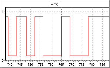
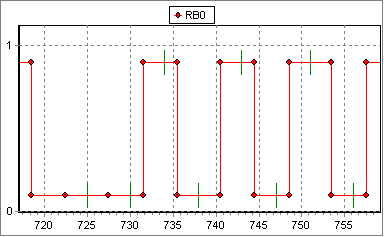
Is it going to work? The simulator shows the following picture, where red points denote bit boundaries and green dashes – read instructions. Because of MP LAB SIM limitations, bit boundaries are aligned to the closest IC boundary and three extra nops added to routine to simulate hardware latency.
Figure 4. Reading at 230400
Weighing anchor
Of course, there is no reason to put this receiver routine code in macro. However, it still makes sense for lower baud rates. These macros would be similar to RS_bodySEND* with few additions – time expired after start bit edge depend on how the application detects start bit and what is done before macro starts. Thus, macro should accept as a parameter number of cycles expired since start bit. Additionally, as the example above indicates, there may be a need of storing data to a different file, not to the predefined one, so this is also added to the parameter's list. With such macro, receiver routine for 115200 would look like:
IV CODE 0x04
| movwf | TMP_WREG | ; 4: save W |
V CODE 0x05
| swapf | STATUS, W | ; 5: load STATUS | |
| movwf | TMP_STATUS | ; 6: save STATUS | |
| btfss | INTCON, INTF | ; 7: what caused this interrupt? | |
| goto | not_INT | ; 8: not INT | |
| clrf | INDF | ; 9: |
RS_bodyRECEIVE .115200, RS_BITCOUNT, RX, 0, INDF, .9
| incf | FSR, F | ; 76: forward buffer pointer | |
| incf | RS_COUNTER, F | ; 77: count this byte | |
| swapf | TMP_STATUS, W | ; 78: | |
| movwf | STATUS | ; 79: restore STATUS | |
| swapf | TMP_WREG, F | ; 80: | |
| swapf | TMP_WREG, W | ; 81: restore W | |
| bcf | INTCON, INTF | ; 82: interrupt handled | |
| retfie | ; 83: leave routine - 2 cycles of one stop bit left |
not_INT
; other handlers
Estimating the speed
As it was shown, the receiver routine has two factors that limit baud rate - bit timing error and start-bit latency. Bit timing error has two constituents, and, being averaged, gives us approximately 1 IC. With this error estimated baud rate limit is BAUD RATE=CLOCK/20 or 200000 baud at 4 MHz. Shortest possible start-bit latency is 4 IC, which gives us BAUD RATE=CLOCK*3/32 » CLOCK/10 or 400000 baud @ 4MHz. Practical start-bit latencies will be longer, so we may conclude that CLOCK/20 is a good estimation for the high limit.
Steering the ship
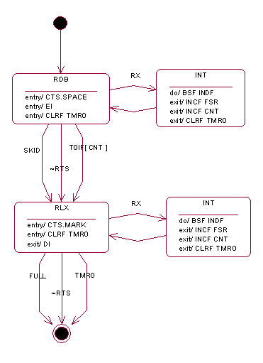
While writing receiver routine, we have assumed that FSR is properly set before an interrupt occurs. This means that PC should start sending data only if PIC is ready to receive them. Another implicit assumption is that PC may stop sending data before the PIC's buffer is overflowed. Since PC application may not be aware of application's state in PIC, latter should somehow indicate these conditions or, in other words, use flow control. RS-232 interface has dedicated lines for hardware flow control: CTS and RTS. According to RS standard (see [7],[8]) PC sets RTS to the SPACE voltage to indicate that more data is ready to be sent. PIC should set CTS to the SPACE voltage when it is ready to receive data. In fact, we are interested in particular implementation of RS-232 on PC running MS Windows. This implementation usually includes a UART chip and the serial port driver. I have not found a well-documented description on hardware flow control in MS Windows. The pieces I have found (see Addendum A) and result of my experiments indicate that despite its hardware name, flow control is actually implemented in software, more specifically, in the serial port driver. A device may enable transmission by setting CTS to SPACE voltage and suspend it by setting to MARK voltage. However, this does not affect data already placed in UART transmit buffer and PC does not stop sending data immediately, it sends reminder of the buffer and stops before a new portion is loaded in the buffer. Another issue is that there is certain delay between events of polling CTS state and loading the buffer. In other words, PC may occasionally miss fact that CTS is already hold MARK and load data to the transmit buffer, which UART will send. PC will detect MARK on CTS after the buffer is already loaded. Receiver routine must take into account all these issues and establish some relaxation period between setting CTS to MARK and exiting. Although, hardware flow control is often assumed as CTS/RTS, RTS line is not that necessary for the flow control as CTS is. Receiver may be implemented with two pins only (RX, CTS). In this case, it should periodically set CTS to SPACE, wait for data to come and exit by timeout. With additional pin for RTS, application may periodically poll RTS (or awake on RTS) and enter receiving routine only if PC has data to send and holds SPACE on RTS. Nevertheless, even with RTS line, receiver should exit by timeout since PC may hold SPACE on RTS permanently4.
Figure 5 . Receiver State Chart
Application
To test these routines we need a test application. This application should work in two modes: testing the transmitter and testing the receiver. First may be done by sending a sequence of characters 0x20-0xFF to the serial port, latter – by reading data form the port and sending them back. To control the operational mode we may use DTR and RTS lines: SPACE on DTR initiates transmitter test, SPACE on RTS initiates receiver test. All unused memory we may use for RS_BUFFER. To prevent occasional overriding by the receiver routine, when the buffer is overflowed, we may place the buffer after all working registers. If such buffer overflow happens, it may be recognized by presence of zeros in the outgoing stream. Receiver routine implements state chart described above with one derivation – at baud rate 230400 CTS is set MARK in the interrupt routine. At this speed, PIC spends less then 10% of CPU (4 cycles of 47) outside of the interrupt routine, which causes essential delay between detecting that the buffer limit is exceeded and suspending transmission. To avoid this problem the buffer is checked and CTS is set in the interrupt routine. Application source is available in Addendum B.
All aboard
Application schema is given on Figure 6. RS-232-to-TTL converter is implemented on discrete parts V1-V4, D4-D6, R1-R11. Negative voltage is taken from DTR and RTS lines via D5 and D6. V1 and V2 converts TTL to RS-232 levels and drives RX and CTS lines. V3 and V4 converts RS-232 levels to TTL and reads TX and RTS lines. Since input pins RB0, RB6 are pulled down, internal week pull-up should be disabled. R11-D4 serves for reading DTR signal (notice, it is not inverted). Transistors V1-V4 can be any small signal p-n-p with Vce > 25V. I have used KT3107L; BC559C may be used instead. D4 is a small power Zener diode, Ust = 3.7-4.7 V, Ist ~= 10mA.
With this implementation, SPACE is logical '0' and MARK is logical '1'. Waveform produced by V1 and V2 is not symmetrical regarding to zero. MARK voltage is about –10V and SPACE is about +5V. Jumpers JP1-JP2 are baud rate selectors (both connected specify 230400). LEDs D1-D2 indicate current state and speed. LED D3 indicates reset and WDT timeout conditions. Pin selection is not critical except the RX pin. Best choice for RX is RB0/INT. If this pin is already in use, a pin with on-change interrupt may also be used. In such case additional care should be taken on ensuring that the interrupt source is RX and that the interrupt flag is cleared after stop bit has started
Figure 6 . UTRS schema
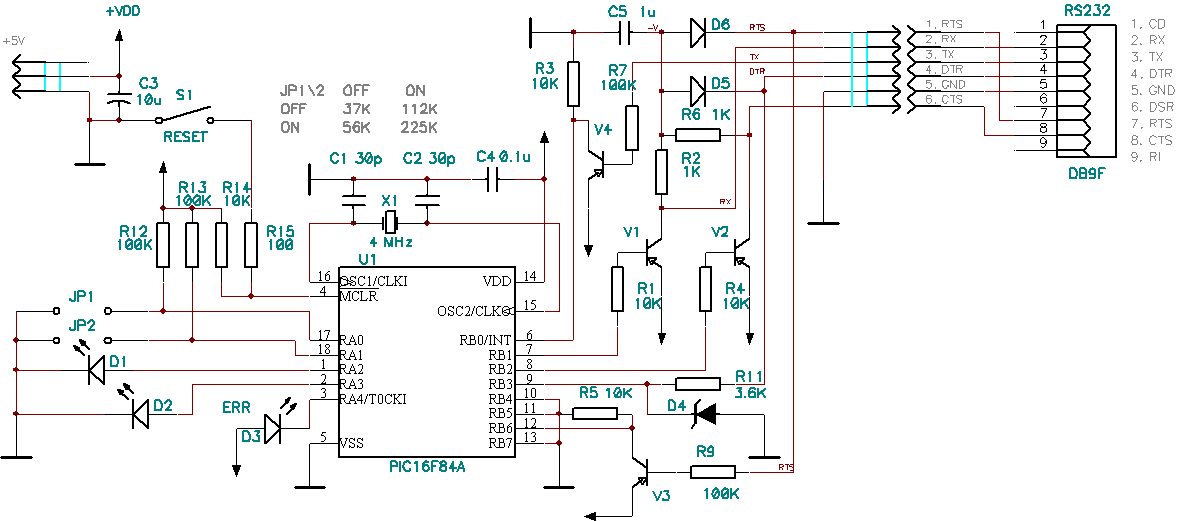
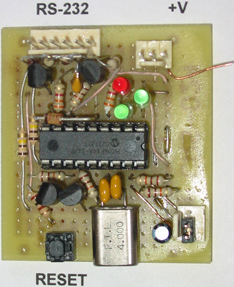
Figure 7. UTRS board
The terminal
Windows API allows setting options for each of RS-232 lines individually (see [10]), however, no one of available communication/terminal programs, which I have looked at, provides explicit control over settings for RTS, CTS and DTR lines. Therefore, I have written a small console application for running communication tests ([11] helped me on this matter). This application sends data to the serial port (either an unlimited sequence of characters or whatever comes into standard input), reads data from the port and writes them to the standard output. As with any console application, its input and output may be redirected from/to a file.
Reviewing trophies
I have loaded UTRS application to a PIC16F84A and tested it on the board. The transmitter routines were working from the very first load. First version of the receiver routines were based on the polling loop and failed at baud rate 230400. Second try with interrupts gave better results but there were frequent cases of skipping several bytes. After several experiments, I have found a relaxation period essential for my PC – 1ms, and my old notebook – 4 ms. I also noticed that Pentium 233 MHz running Win98 is not powerful enough to read the 115200 stream.
Addendum A
This addendum lists nuggets of information that hinted me about software implementation of hardware flow control. Doc on UART ([9], page 11)
CTS, Clear to Send, Pin 36: When low, this indicates that the MODEM or data set is ready to exchange data. The CTS signal is a MODEM status input whose conditions can be tested by the CPU reading bit 4 (CTS) of the MODEM Status Register. Bit 4 is the complement of the CTS signal. Bit 0 (DCTS) of the MODEM Status Register indicates whether the CTS input has changed state since the previous reading of the MODEM Status Register. CTS has no effect on the Transmitter.
MSDN, Requirements for the serial port in a Windows Thin Client device.
The serial port must meet flow-control requirements.
Hardware flow control that uses Request To Send (RTS) and Clear To Send (CTS) must be supported. Data Terminal Ready (DTR) and Data Set Ready (DSR) hardware flow control is optional. Software flow control must be supported, including the capability to support a clean stop in transmission of the current buffer. Supporting such a clean stop is more challenging for implementations that support large direct memory access (DMA) buffers than it is for implementations that use small serial ports that are based on the first in, first out (FIFO) method.
The serial port must support a maximum skid of 16 bytes; this is the maximum number of bytes that continue to be sent after the receiver requests a flow control off command.
During my experiments I found out that this number of bytes depends on UART transmit buffer length specified at port configuration. This parameter is not applied immediately but only after a reboot.
WinAPI function SetCommState and DCB structure (see [10])
fOutxCtsFlow
If this member is TRUE, the CTS (clear-to-send) signal is monitored for output flow control. If this member is TRUE and CTS is turned off, output is suspended until CTS is sent again
Addendum B
|
SRC |
Application sources (including MP LAB IDE project) |
|
RS.ASM |
An example of using RS_bodySEND, RS_bodyRECEIVE macros. |
|
UTRS.HEX |
A compiled and ready to load PIC application |
|
TESTS |
The console terminal application with a set of tests |
References
[1] 500kbps @ 4MHz; Regulus Berdin
http://www.piclist.com/techref/microchip/rs232at500kbps.htm
[2] SPBRG Calc
http://www.piclist.com/techref/microchip/spbrgcalc.asp?fOSCILLATOR=4&fErr=20
[3] HiSerial.sys High speed serial port driver, André Rippstein
http://www.rippstein.net/HiSerialEN.htm
[4] PIC16F84A Data Sheet, Microchip
[5] PICmicro™ Mid-Range MCU Family Reference Manual; Microchip
[6] Serial HOWTO; David S.Lawyer original by Greg Hankins
http://www.ibiblio.org/mdw/HOWTO/Serial-HOWTO-3.html
[7] The RS232 Standard; Christopher E. Strangio
http://www.camiresearch.com/Data_Com_Basics/RS232_standard.html
[8] Serial Programming Guide for POSIX Compliant Operating Systems; Michael Sweet
http://www.rebel.net/~mad/serialtutor/rs232.html
[9] PC16550D Universal Asynchronous Receiver/Transmitter with FIFOs; National Semiconductor
https://www.ourpcb.com/what-happened-to-national-com.html
[10] Platform SDK: Device I/O, DCB; Microsoft
http://msdn.microsoft.com/library/default.asp?url=/library/en-us/devio/base/dcb_str.asp
[11] Serial Communications in Win32; Allen Denver
http://msdn.microsoft.com/library/default.asp?url=/library/en-us/dnfiles/html/msdn_serial.asp
Post a Comment