SISAM Hardware schematic is given on Figure 1.
Besides the MCU PIC16F690 it includes a 20 MHz crystal and a RS232 matching circuit.
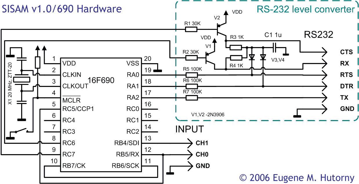
Figure 1. SISAM Hardware Schematic
Channel 0 input is wired to RB5 and RC5, channel 1 – to RB4.
Actuator outputs are connected to RC0-RC4 (wirings are not drawn on this schema).
Wire RB6-RB7 delivers clock from EUSART to SSP.
RS232 matching circuit
It is implemented on discrete elements and does not require -12V supply.
Inputs (RTS/DTR/RX) are implemented with current limiting resistors 100K. This design makes SPACE equal to logical "1" and MARK – to logical "0".
Outputs (TX/CTS) are implemented with discrete inverters built on PNP transistors V1, V2 and current limiting resistors. With this design SPACE is set by driving output pin to "0" and MARK – to "1". Output level inversion is performed in the firmware.
-12 V is derived from RTS or DTR line via V3, V4. This design requires at least one of these pins to be in MARK state.
Firmware
SISAM v1.0 Firmware is available for download
Board
I have used Microchip Low Pin Count Demo Board (LPCDB) that comes with PICkit 2.0.
The only modification required to the original LPCDB wiring – R7 has to be physically disconnected.
Because pins used for in-circuit programming are wired via 100K resistors, this design is safe to use with in-circuit programming. There is no need to disconnect the programmer to test the device.
Note on cabling.
Basically, inverters V1 and V2 are loaded with whatever cable you use to connect this device to your PC. This cable has some capacitance and this capacitance limits the communication speed. To work properly on high speed (460K and above) cable capacitance must not exceed 30 p. This may not be achievable with a regular RS232 cable 1.5 m long. Thus, keep the cable as short as possible or use a different design for RS232 matching circuit.
Please find test results on various RS232 Level Converters in this post
One Comment