Previous examples illustrated VELOOS programming aspects. This post provides an example of using object oriented paradigm for designing VELOOS application. Unlike the previous examples which were purely programming exercises, this example is dedicated to a utilitarian home appliance application and provides a "reference design" for VELOOS applications.
Example3 – Designing MIHA – Multi Input Hall Automaton
Introduction
There are two common approaches for light switching in halls and staircases – off-timers and intermediate switching schemes (please excuse me if terminology is wrong). Off timers turn light on when user pushes a button and turn off when specified time elapsed. Intermediate switching schemes toggle lights when user toggles any switch (of two). Each approach has its own advantages and disadvantages, however, both approaches require special switches, which could be an undesired constraint for interior design. See, for example, Intermediate lighting switch, Stair case timer, Multifunction staircase timer
Requirements (user’s needs)
Implement a light-control appliance that:
- combines off-timer and intermediate switchers
- provides support for at least 3 switches
- supports regular light switches as well as push-buttons
- provides settable 0.5-10 min timer range with a simple user interface for entering value
MIHA Design Description
Key Design Decisions:
- Implement the appliance (named MIHA) as a VELOOS application running on a PIC microcontroller
- Store application configuration in EEPROM during device programming
- Use potentiometer for specifying timeout
Architecture
MIHA consists of the following units (see architecture diagram on Figure 1):
| Multi-input Switch Debouncer | Reads and debounces switches, sends a message on switch state changing. Featuring triple port read with majority logic and software implementation of RC-integration and Schmidt trigger. |
| Hall Light Automaton | Implements automaton logic, provides supports for switches/push-buttons, send ‘alt’ message to actuator and ‘off’ message to the delay block |
| Delay Time Input | Reads potentiometer value and sends the value read to the delay block Featuring support for multiple channels. ADC access is arbitrated via time quantization |
| Message Delay Block | Provides delay for the ‘off’ message. |
| Discrete Actuator | Turns on or off an output pin depending on the message received |
|
Mapping Architecture to Implementation. |
 Figure 1. |
|
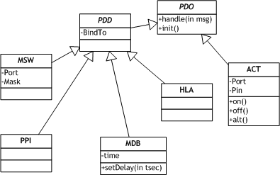 Figure 2. |
Moduling
Major advantage provided by VELOOS is ability to design and implement loosely coupled objects. The following practice can be applied to get full advantage of loose coupling:
- A unit should be made up of (at least) two files: (1) .inc containing interface and (2) .asm – implementation
- Each unit should implement one class or a hierarchy of closely related classes.
- A unit should not instantiate objects of reenterable or configurable classes. Instead it should publish class name in the interface.
- A unit may instantiate object of a non-reenterable class. In this case it should publish object name and encapsulate class name.
Sharing RAM among objects
Decoupling objects via messaging mechanism provides a very explicit and straightforward watershed for scoping variables – everything that should survive between two messages is a part of object state and should be allocated in udata section, everything that may be discarded after handling the message is a temporary variable and can be allocated in udata_ovr section.
Using Timer for Resource Access Arbitration
Class Potentiometer Parameter Input (PPI) implements time-quantified approach for sharing ADC among several instances – time is sliced on N quants, each instance may access hardware only if TIME mod N equals to channel number. To simplify computing TIME mod N, N can be chosen as power of 2. In this example N = 16.
Multi-input DebouncerOn timer event Debouncer polls the port three times in a row and applies majority logic to determine current switch state. This approach eliminates sporadic spikes than may be present in a noisy environment. For each assigned pin it maintains a counter. This counter is incremented whenever pin level is high and decremented if low. Counter is maintained in range 0..16, e.g. when it reaches the boundary it is not changed. When counter reaches upper threshold (12) logical output state is changed to 1 and to 0 when it reaches lower threshold. This is a software model of an RC-integration connected to a Schmidt trigger. Hardware SchematicMIHA schematic is shown on Figure 6. Relay, loaded on PIC12, should have actuating current up to 25 mA. Resistors R1-R4 are used for pull-up and can be roughly 1 kOhm. In an environment with strong EMI their can be reduced to avoid pickup. Package ContentThe package includes three projects to build this application for three different devices – PIC12F675, PIC16F690, PIC18F248. It is licensed to public under the Open Software License |
Figure 3. |
|
Figure 4. |
||
Figure 5. |
||
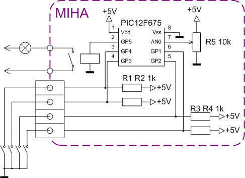 Figure 6. |
Post a Comment