First flight-shot
Let’s make our transmitter routine, assuming that the data byte is passed in W, inserting delay n instead of nop delays.
| movwf | data | ; put data to rotation buffer | |
| rrf | data, W | ; prepare data for output: | |
| bcf | port, 0 | ; 0: sending start bit | |
| xorwf | data, F | ; 1: '1' in DATA means toggle port | |
| movlw | 1 | ; 2: load port-toggling mask | |
| skpnc | ; 3: first bit is already in C | ||
| xorwf | port, F | ; 4: send bit 0 | |
| delay | 3 | ; 5, 6, 7 | |
| btfsc | data, 0 | ; 8: test data | |
| xorwf | port, F | ; 9: send bit 1 | |
| delay | 2 | ; 10, 11 | |
| btfsc | data, 1 | ; 12: test data | |
| xorwf | port, F | ; 13: send bit 2 | |
| delay | 2 | ; 14, 15 | |
| btfsc | data, 2 | ; 16: test data | |
| xorwf | port, F | ; 17: send bit 3 | |
| delay | 3 | ; 18, 19, 20 | |
| btfsc | data, 3 | ; 21: test data | |
| xorwf | port, F | ; 22: send bit 4 | |
| delay | 2 | ; 23, 24 | |
| btfsc | data, 4 | ; 25: test data | |
| xorwf | port, F | ; 26: send bit 5 | |
| delay | 2 | ; 27, 28 | |
| btfsc | data, 5 | ; 29: test data | |
| xorwf | port, F | ; 30: send bit 6 | |
| delay | 3 | ; 31, 32, 33 | |
| btfsc | data, 6 | ; 34: test data | |
| xorwf | port, F | ; 35: send bit 7 | |
| delay | 3 | ; 36, 37, 38 | |
| bsf | port, 0 | ; 39: sending stop bit | |
| return |
As we now see, this routine needs delays for 2 and 3 instruction cycles. If we use simple nop to make delays, it would take additional 20 words of program memory making routine 43 words long. Let us consider alternatives to save a word or two.
| movwf | data | ; put data to rotation buffer | |
| rrf | data, W | ; prepare data for output: | |
| bcf | port, 0 | ; 0: sending start bit | |
| xorwf | data, F | ; 1: '1' in DATA means toggle port | |
| movlw | 1 | ; 2: load port-toggling mask | |
| skpnc | ; 3: first bit is already in C | ||
| xorwf | port, F | ; 4: send bit 0 | |
| goto | $+1 | ||
| nop | |||
| btfsc | data, 0 | ; 8: test data | |
| xorwf | port, F | ; 9: send bit 1 | |
| goto | $+1 | ||
| ... | |||
| btfsc | data, 6 | ; 34: test data | |
| xorwf | port, F | ; 35: send bit 7 | |
| goto | $+1 | ||
| nop | |||
| bsf | port, 0 | ; 39: sending stop bit | |
| return | ; Routine length: 35 words |
Sighting the limits
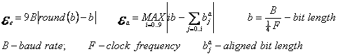
What is the highest speed one may achieve with this approach? Marginal timing error 20% is reached when it is equal to a half of the instruction cycle, which gives 2.5 IC per bit or 400000 baud. Generalizing, we may say that BAUD RATE = CLOCK/10 is the estimated limit. What is the lowest speed that requires bit aligning? The problems begin when cumulative timing error reaches 20%. Averaging bit error to 0.5 IC, we get equality †9/2 IC = bit*0.2 that gives us 22.5 cycles per bit, or 44K baud @ 4 MHz and 178K baud @ 10 MHz. Of course, it depends on rate/clock ratio and, for some particular cases, there may be no need in bit alignment. Table 2 shows timing errors1 with equal and aligned loops for two most used clock frequencies and five highest baud rates. For comparison purposes, it also lists lowest bit errors achieved with hardware UART2.
Post a Comment