Together with WREG loading, it takes W*4+4 cycles and has limit of 1028 IC and precision of 4 IC. We may enhance its precision with additional entries:
RS_DELAY3WC
nop
RS_DELAY2WC
nop
RS_DELAY1WC
nop
RS_DELAY0WC
...
| movlw | n/4 | |
| call | RS_DELAY<n&3>WC |
To provide RS_bodySEND macro with proper delay routines we may add code to RS_delay macro that will collect all needed entries by setting a flag in a constant and define RS_delays macro that will examine this constant and generate only needed delay routines and their entries, saving code space. With all these tricks, application code will look like this:
#define CLOCK .4000000
RS_SEND225K

     RS_bodySEND .230400, .8, PORTA, 1, 0

     return

     RS_delays
Simulating waves
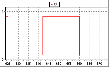
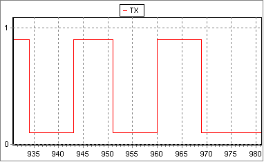
It is time to see if these routines will work at all. For this purpose I have created a unit test application that, depending on selection, outputs data with baud rates 57600, 115200 and 230400 and ran it in the simulator. Simulator traces are then visualized with self-made SIMCHART application and are shown on figures 1-3. They appear to be OK. Will they work in silicone? They should, but let us defer this question and consider the receiver routine first.
Figure 1. 57600, start bit (17IC) and bit0 (18IC)

Figure 2. 115200, start bit (9IC), bit0 (8IC), bit1 (9IC), bit2 (9IC)

Post a Comment