Jettisoning the ballast
Bits must be read at 6 11 15 19 24 28 32 37 cycles since start bit falling edge, which means at 3 8 … 34 instruction cycle of the routine. To read bits we will use the following instructions:
| btfsc | RX | ; test port | |
| bsf | INDF,<i> | ; set bit | |
| nop | ; delay | ||
| nop | ; delay |
As everyone may see, among 37 instructions spent on byte reading, only 16 are "productive", the others are just ballast, which we may replace with something useful, like saving context, incrementing byte counter, etc. It is important to notice, that bit-reading instructions do not affect STATUS so we may save it later, just before incrementing FSR or the counter. On the other hand, we cannot modify INDF before we ensure that the interrupt is caused by RX pin and cannot clear working file (INDF) with clrf before STATUS is saved. The following code sample solves all these issues:
IV CODE 0x04
| movwf | TMP_WREG | ; 4: save W |
V CODE 0x05
| movlw | 0 | ; 5: safely clear W | |
| btfsc | RX | ; 6: test port RX | |
| movlw | 1 | ; 7: set bit 0 | |
| btfss | INTCON, INTF | ; 8: now we have some time to look what caused this interrupt | |
| goto | not_INT | ; 9: not INT | |
| movwf | INDF | ; 10: save what already recived to buffer (clrf replacement) | |
| btfsc | RX | ; 11: test port | |
| bsf | INDF,1 | ; 12: set bit 1 | |
| nope | ; 13, 14 | ||
| btfsc | RX | ; 15: test port | |
| bsf | INDF,2 | ; 16: set bit 2 | |
| swapf | STATUS, W | ; 17: load STATUS | |
| movwf | TMP_STATUS | ; 18: save STATUS | |
| btfsc | RX | ; 19: test port | |
| bsf | INDF,3 | ; 20: set bit | |
| incf | RS_COUNTER, F | ; 21: already safe to increment counter | |
| movf | TMP_WREG, W | ; 22: W is not used we may restore WREG | |
| nop | ; 23: | ||
| btfsc | RX | ; 24: test port | |
| bsf | INDF,4 | ; 25: set bit | |
| nope | ; 26, 27 still have plenty of time | ||
| btfsc | RX | ; 28: test port | |
| bsf | INDF,5 | ; 29: set bit | |
| nope | ; 30, 31 | ||
| btfsc | RX | ; 32: test port | |
| bsf | INDF,6 | ; 33: set bit | |
| nope | ; 34, 35 | ||
| nop | ; 36 | ||
| btfsc | RX | ; 37: test port | |
| bsf | INDF,7 | ; 38: set the last bit | |
| incf | FSR, F | ; 39: advance current position, Z is discarded with 0 (FSR>0) | |
| btfsc | TMP_STATUS, (Z+.4) | ; 40: what was the last saved value of Z? | |
| setz | ; 41: restore Z, it was the only flag discarded | ||
| bcf | INTCON, INTF | ; 42: interrupt handled | |
| retfie | ; 43: leave routine - 4 cycles of two stop bits left !!! |
not_INT
; other handlers
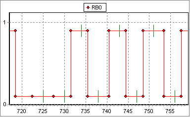
Is it going to work? The simulator shows the following picture, where red points denote bit boundaries and green dashes – read instructions. Because of MP LAB SIM limitations, bit boundaries are aligned to the closest IC boundary and three extra nops added to routine to simulate hardware latency.
Figure 4. Reading at 230400
Post a Comment